Archive for category Electronics Devices and IC's
DTMF Tones Info
Posted by akshayadiga in Electronics Devices and IC's on December 14, 2009
DID YOU KNOW ?
Tone Duration = 40ms
Tone Pause = 40ms
DID YOU KNOW ?
A normal DTMF detector uses a 9th order bandpass Filter
What is the Difference Between Vcc, Vdd,Vss,Vee?
Posted by akshayadiga in Electronics Devices and IC's on December 14, 2009
Common supply terms has been blurred by the interchangeable application of TTL and CMOS logic families
But, the Fact is ,
Vcc and Vee are the terms used for Transistors .
Vdd and Vss are the terms used for FET’s
And in terms of supply voltages :
Vcc and Vdd is for positive supply.
Vee and Vss is for negetive supply.
Apparently this terminology originated in some way from the terminals of each type (i.e., Vcc is often applied to BJT collectors, Vee to BJT emitters, Vdd to FET drains, and Vss to FET sources). This notation then carries across to integrated circuits — TTL ICs were originally based on BJT technology, and so often use the Vcc / Vee terminology;
CMOS ICs are based on FET technology, and so often use the Vdd / Vss terminology.
Switched Capacitor Filters
Posted by akshayadiga in Electronics Devices and IC's on December 14, 2009
This a modern design for Filters used in the IC fabrication as they donot require “Resistors”.
Why Switched capacitor filters ?
Basically,
1) The problem with the resistors is that they take up a lot of room in the IC ,
2) Precision is enhanced ,as two capacitors are compared, hence the manufacturing errors are somewhat masked.
so this alternative has been taken up.
How does it work?
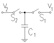
To understand how switched capacitor circuits work, consider the circuit shown with a capacitor connected to two switches and two different voltages.
If S2 closes with S1 open, then S1 closes with switch S2 open, a charge (q is transferred from v2 to v1 with

If this switching process is repeated N times in a time (t, the amount of charge transferred per unit time is given by
.

Recognizing that the left hand side represents charge per unit time, or current, and the the number of cycles per unit time is the switching frequency (or clock frequency, fCLK) we can rewrite the equation as
.

Rearranging we get
,

which states that the switched capacitor is equivalent to a resistor. The value of this resistor decreases with increasing switching frequency or increasing capacitance, as either will increase the amount of charge transfered from v2 to v1 in a given time.
Where is it used ?
for the mean time, band-split filters and related applications
